Mechanical Design
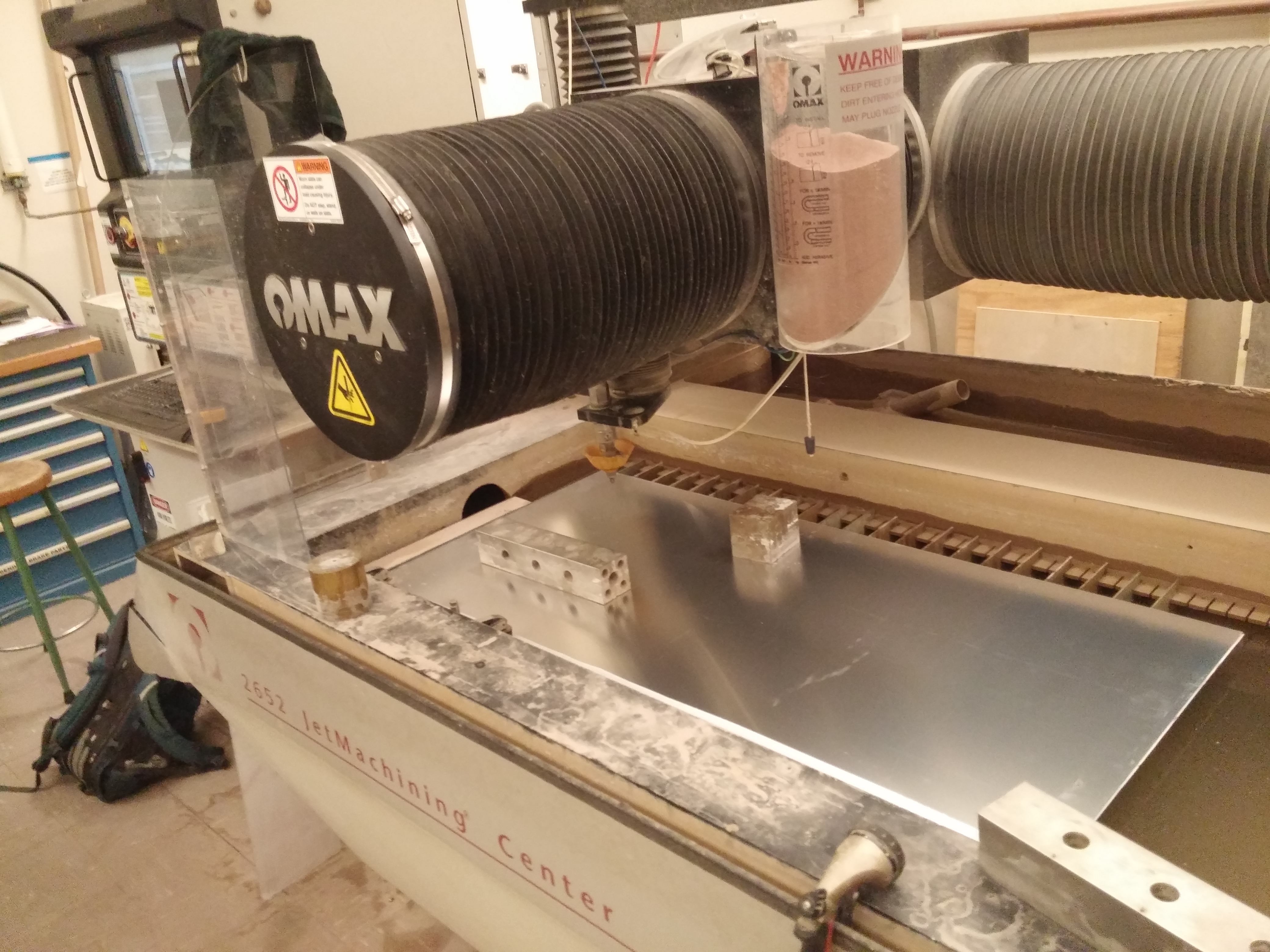
Mechanical components for the robot were designed in SolidWorks and produced using CNC machining via waterjet cutter and lasercutter. The overall design of the robot is bi-directional, to reduce the time required to turn around. As a result our robot is mechanically symmetric about its drive axle, which is located at the center of the robot chassis. Two unpowered wheels at front and back provide a 4-point base for stability.
The Chassis
Fighting Squid chassis consisted of 4 major components: top plate, bottom plate, and two brackets which mounted the top and bottom plate together, and also housed the bearings used for the drive train. The bottom and top plates were waterjet cut from 2mm thick Aluminum and 1/4" polycarbonate, respectively
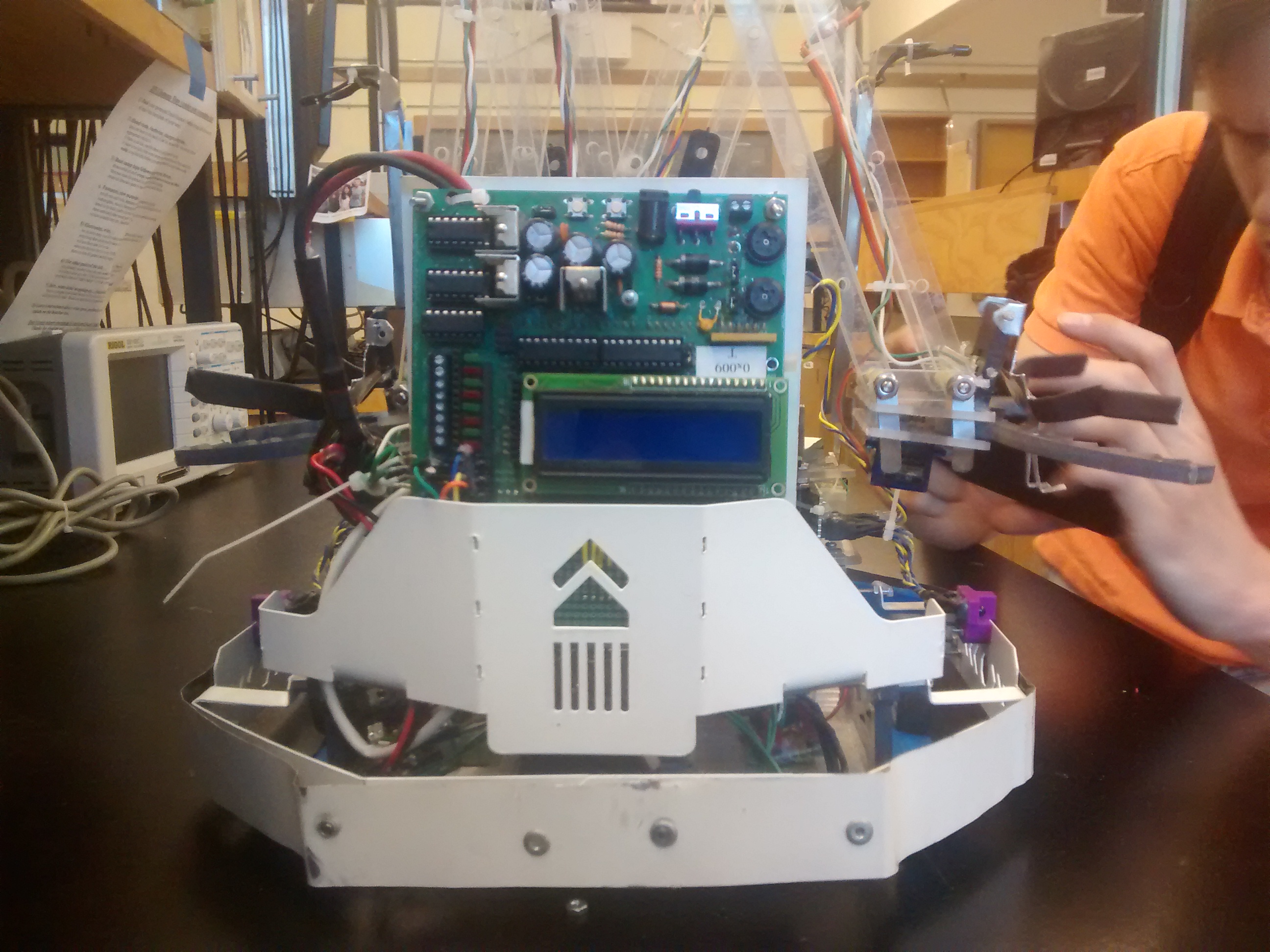
The Pickup Arm
The arm pickup mechanism consists of two one-degree of freedom arms which share a common base, and each have a servo-actuated grabbing claw. Fighting Squid is able to use either arm to pickup a passenger, rotating as necessary to align whichever arm is free.
The arm was a lot of fun to construct and test out, as you can see from the video below
The Drive-Train
The drivetrain used two Ungeared Barber-Coleman motors delivering 45 Ncm of torque to two 4.5cm diameter wheels cut from polycarbonate. Gears were lasercut from polycarbonate to prove a 1:1.2 ratio between drive and wheel, which were housed in a 608 bearing press-fit into the main chassis bracket which connects the upper part of the robot chassis to the bottom. Here is a video showing the early version of the drivetrain.